| |
Annotating a structure
|
|
| |
This chapter describes the features of Cn3D that are used to annotate a structure with labels and drawing styles, to create static image files, and to save work to Cn3D-style (ASN1) data files to reload in another session or to use as interactive figures in an electronic publication.
|
|
| |
Backbone and termini labels
|
 |
| |
The controls on the style panel's Labels tab (see Style:Edit Global Style) let one place text labels automatically at various points along the amino acid or nucleotide chain. The Spacing dictate the interval between labels - e.g. on every fifth residue, every twentieth, etc. Type says whether to use one or three letter residue abbreviations, and Numbering lets one choose sequential numbers (1..N along the sequence), PDB-assigned residue numbers, or none. Labels will be in a color that's visible against the background if Contrast with backbone is checked, otherwise will assume the color of the residue's backbone. Labels on chain Termini and Metal Ions can be controlled here as well.
While automatic labeling is convenient, especially for large structures, there are many cases where one might want to label and highlight individual, user-selected residues. This is the subject of the next section.
|
|
| |
User-defined styles
|
|
| |
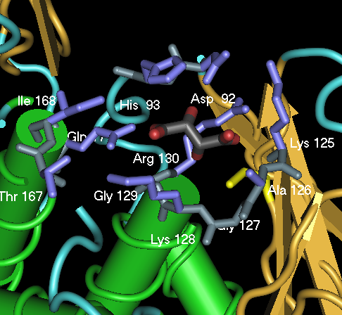
Suppose Cn3D is being used to create a figure depicting the active site of a protein. The user might wish to highlight specific amino acids known to participate in binding and catalysis, using labels and contrasting drawing styles to distinguish those residues clearly against the rest of the structure.
This type of specialized annotation is accomplished via the Style:Annotate dialog. This allows the user to apply labeling and drawing settings - different from the global settings - to residues that have been selected (highlighted) in either the sequence or structure window.
Let's return again to the human PTEN crystal structure. Cn3D can be used to create a figure that looks somewhat like Figure 2D from Lee et al., 1999, showing the active site side chains around the inhibitor:
 ... or click here to launch this figure in Cn3D ... or click here to launch this figure in Cn3D
The procedure to create a special annotation style is:
- Highlight the appropriate residues by selecting them in the sequence window or double-clicking on them in the structure window.
- Go to the Style:Annotate dialog, and hit New. Fill in a name and a description for this feature. Hit Edit Style to bring up the style panel, which will now apply only to the selected residues. Set drawing and labeling styles as desired, probably something that contrasts with the global style (the style applied to everything not in a specific annotation). Changes will be immediately shown in the structure window.
- Hit "Done" in the style panel, then "OK" to create and display the annotation.
The annotation sample above shows how the Annotate dialog was used to create a binding pocket annotation to label and render those specific residues. Also included is a second annotation that colors the catalytic cysteine (C124) yellow.
The drawing and labeling settings for an annotation can be changed by selecting a feature in the list on the left and hitting Edit and then Edit Style to bring up the style panel for that annotation; make the desired changes then hit "Done" to save and show the new settings. Delete will remove an annotation, and Move will move the annotation settings instead to any residues highlighted at the time it is pressed. Individual annotations can be hidden by selecting them in the list on right and hitting Turn Off, then shown again by selecting in the list on the left and hitting Turn On.
|
|
| |
Saving structures and images
|
|
| |
There are two types of file output from Cn3D: static images and data files. Each has its advantages and disadvantages, as discussed below. These features were used to create many of the images and interactive figures in this document.
The File:Export PNG command saves the current contents of the structure drawing area to a PNG format image file, which by default has the same pixel dimensions as the original, but can be saved to a much larger high-resolution file, e.g. for hardcopy. These files can be viewed by most modern web browsers and word processors, and because of their good data compression and full color support, are ideal for inclusion in electronic publications.
The File:Save command saves the current view to an ASN1 data file, which is the type of data Cn3D reads. The resulting file contains all the structure and sequence information present in the original data, along with the current model orientation (rotation/zoom), any additional sequences imported, global drawing and labeling settings, and user-defined annotations (as discussed above). This serves two purposes: first, it lets one save one's work to a file, as with word processors or other editing software, to store for retrieval in a later session. Second, and perhaps more importantly, it lets one use a saved Cn3D session as an interactive figure, which is the subject of the next section.
|
|
| |
Using Cn3D for interactive figures
|
|
| |
Throughout this tutorial there appear examples of "interactive figures:" images with links to downloadable data, that when loaded into Cn3D, reproduce the image within the interactive environment of Cn3D's interface. Thus one can prepare a static image that can be used as a traditional illustration in a digital publication, with the advantage that the user can further explore the structure(s) and sequence(s) by loading the data into Cn3D. Then when the program is launched with this data, the initial view will be the same as in the static image, giving the user a good starting point to interactively investigate the information being presented.
This is very easy to do: use File:Export PNG and File:Save to create the static image and data file, respectively, without changing the structure between these operations. Then link the data file to the image in some context with the ability launch Cn3D with the name of the data file as the command line argument.
In a web page, simply use the usual anchor link mechanism to attach the data to the image. Using the example from above, click on the image to load the same figure and view into Cn3D:
The more complicated part is setting up the web server to send the data with the correct mime type, so that the user's browser knows to launch Cn3D on the downloaded data. NCBI currently uses Apache, which is controlled by a .htaccess file with the line:
AddType chemical/ncbi-asn1-binary .cn3
This tells Apache to send files with the .cn3 ending as the mime type chemical/ncbi-asn1-binary that a web browser uses to launch Cn3D. Other web servers may have different mechanisms to do the same thing; consult the server's documentation for more information.
|
|